Transmitter Operations - Reminiscences
Brookmans Park -
Pictures and Memories
by Peter Gutteridge (BP 1970 - 1974)
Click on the thumbnails to enlarge the pictures and use the browser's Back button to return.
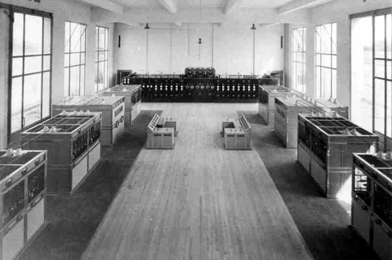
The main transmitter hall, probably photographed shortly after installation of the transmitters in 1929.

The
main transmitter hall taken from the upper corridor that has the front upstairs
room off it. c1970
The BBC's first transmitter "2LO"
was rebuilt at Brookmans park and it can be seen in the foreground.

This picture shows the 240v lead acid cell battery room. It shows someone checking the cells, disregarding the goggles and large rubber apron that safety regs made me wear. One of the jobs was to poke a rod down between the plates. The top of the cell was completely open and the idea was to clear the growths that came out from the plates. If they bridged the gap between two plates, then the cell output would be low. Mind you, if you wore the goggles, the reflections on the surface of the electrolyte made it impossible to see right down to the bottom.

There were four engines, three of which could supply the power for the two regional transmitters.
They produced 240v DC, so in the event of an incoming mains supply failure, they could not power the newer transmitters that were added in 1962. The old transmitters remained in reserve and it used to amuse me that when the Radio 1 transmitter failed, the up to the minute trendy programme was carried by a 1929 transmitter and diesel.
The diesels were started by compressed air and I took it as a challenge to start all three engines off one air bottle. It could have been laziness, because then I would not have to change the bottles over. It was a challenge because if you left it too long after the air got them turning to let down the valves then you wasted air, but if you did it too soon the engine would not start. Then, to restart, you had to get a 6 foot bar of steel, and use slots in the flywheel to lever it round to the starting position, and then try again. Of course, you were moaned at for making the start up take longer.
I think it took 20 minutes to get the transmitters started after a mains failure.
Once the engines were running, and the output connected to the board, you had to make sure that the diesel tanks were topped up, the water pumps were going (the water, which you had to put on before starting the engines was fed by gravity from a tank, so pumps were needed to top up the tank) and use a large oil can to lubricate the moving valve gear. You had to stand on the catwalk along each engine, feeling like Casey Jones.

Subsequent safety rules meant that the flywheels had to be cased in, as shown on this picture. They used to have fairly shiny rims, with red painted spokes, and when they were spinning up to speed with the sunlight streaming through on to them they looked fantastic. They looked less good encased in grey metal!

This is a drawing of the HT generators.
They were dynamos that produced 11000 volts DC to provide the High Tension supply for the transmitter valves. The shafts were driven by 240v DC motors. The 240v came from the engines, or from the batteries or from a mercury arc (I think) rectifier producing 240v DC from the incoming mains.
There was a key based interlock system that prevented the gates in the fencing being opened when they were on.
To start them up, there was a control panel along one of the walls. There was a large switch with a big handle to pull down to connect the 240v DC. Then there was a row of copper blades with black insulating handles. These allowed power to be applied gradually to the machines. You had to close the first switch and then the second almost immediately afterwards, one with each hand. You had to do it smartly, otherwise an arc would be struck across the gap of a nearly closed switch, which could burn or melt the copper. (There was 240v DC on them - safety rules had not got as far as these controls. ) The machine would slowly start to revolve, and when you thought it had got fast enough, you whacked in the next copper blade switch, and as the machine got still faster you put in the next until they were all in.
As you might gather, running these old transmitters was quite an art - not like just pressing the on button on the modern transmitters and letting it all happen.

These generators supplied the filaments.

The smaller machines supplied other voltages (415, I think).
They were no trouble to start, you just switched them on as far as I remember.
![]()
The first cabinet on the left was the first amplifying stage. Originally, it had a circuit that oscillated and provided the RF drive for the transmitter. Later on, this oscillation was derived from crystal oscillators in a special drive room. I was always intrigued by labels that were left over from the original referring to the 'fork drive'. The manual says that the 'tuning fork drive did not prove entirely satisfactory'.
The unit with the two 'steering wheels' contained capacitors that would tune the transmitter to the aerial. T he output would go up a pair of wires to the feed through insulators on the wall above, but they are not shown in the picture, so I assume it was taken before the transmitter was functional.
Each side of this unit was the power unit. They each contained 8 valves. One was a spare, and the other 7 ran in parallel to provide the power in a push pull arrangement with the other 7 valves.
The valves were water cooled.
Before applying HT, the filaments had to be switched on. As with all the other parts of the system, it was up to the operator to set the voltage they were ran at, and how long to let them warm up before moving on to the next stage.
![]()
This picture shows where an extension was built along one side of the old hall. 2LO is on the right.
The 1939 transmitter was installed in the extension. The various gauges and meters had unusual legends on them, for example, the water flow was measured in 'litrus'. I understand that this transmitter was built for Lithuania (I think) but when war broke out it went instead to Brookmans Park.

I did not have much to do with the 'outside'. We had a rigger called Dennis who looked after that. Sometimes we would have to spend the night adjusting the components in the aerial tuning hut, to make sure that the power from the transmitter was properly transferred to the aerial.
Alongside the building was the cooling pond for the valve cooling water. The distilled water for cooling the valves was pumped around the valves and then (I think) through pipes surrounded by water jackets. The water in these jackets was pumped out to the pond, which had large goldfish in it. The water was sprayed up into the air through nozzles in the centre of the pond to cool it. Every now and then the nozzles would get blocked. We had a 20 foot pole with a nail in the end, and had to try and get the nail down the nozzle that wasn't working properly and wiggle it round to clear it. Unfortunately the pole was a bit flexible, and very long, so the end waved around a lot, and was very hard to get in the nozzle before your arms got too tired to manoeuvre it.
It wasn't easy being a MW transmitter engineer!
The engine cooling water went through pipes in a large construction at the back of the building. There was a slatted wooden 'shed', around 20 feet high built over these pipes, and the secondary cooling water was pumped up and then ran down the slatted wooden tower, over the pipes.


While I am reminiscing, I remember poking about one night in the old archives and finding references in old memos to tests that the old regional transmitters were carrying out. I think the date was around 1930 and I seem to remember that the idea was that one transmitter carried sound and the other vision for experimental television services.


A 'medal' that was issued to commemorate 50 years of broadcasting from the site.
These links provide further information about Brookmans Park:-
Brookmans Park.
The London Twin-Wave Broadcasting Station,
A Descriptive
BBC Souvenir 1930.
A History of Brookmans Park Transmitting Station
By Lilian Caras 1982 (revised January
2002)